
Comparing Digital and Physical Gauges
BendingStudio software is a powerful tool to assess the dimensional conformity of formed tubes and tubular assemblies. It has many capabilities and plenty of flexibility to handle different types of products and inspection goals. Regardless of what kind of tube you intend to inspect, an essential first step when inspecting a formed tube in BendingStudio software is to set up an Inspection plan. The Inspection Plan defines how the tube will be inspected, including:
- Which Components are included
- What Inspection Criteria will be evaluated
- The Alignment of the measured tube to the nominal tube
- The Measurement Device used for the inspection.
This article describes the importance of being deliberate about how the Alignment is set up for your new Inspection Plan.
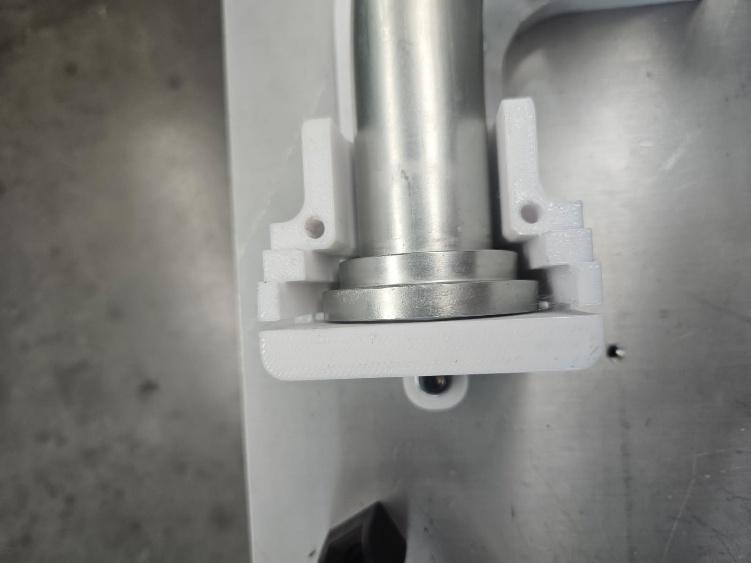
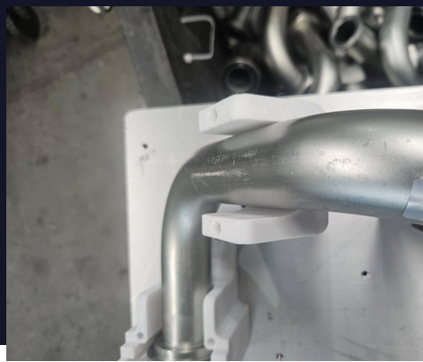
Consider the following example. A customer produced a tube with some end fittings and then placed it in a checking fixture (hard gauge) after bending to check its geometry. The part fit into the gauge – that is good. However, when inspecting the same tube in their TubeInspect system with BendingStudio software, the part failed inspection – not good. The TubeInspect result shows that the shape of the is very good, but the B end of the part is a bit too long. Naturally, the customer was puzzled as to why the part failed inspection on TubeInspect but passed on their gauge.
The first step of the investigation was to check the inspection criteria. Are both inspection methods checking the same things? The checking fixture was built to allow a certain tolerance around the outside profile of the final part. This type of inspection is represented directly in BendingStudio by using a “sheath tolerance” inspection criteria. The BendingStudio inspection plan in this case was using the specified sheath tolerance which corresponded directly to the gauge tolerance. Therefore, the inspection criteria were correct.
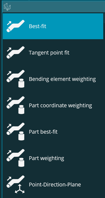
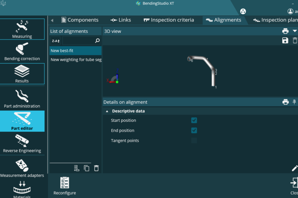
The second consideration is the alignment used in the inspection. There are several options for alignment in BendingStudio including multiple versions of best fit, various fit weightings and 3-2-1 alignments. When creating a new alignment in BendingStudio, the default is a classic best fit alignment on the tube centerline. This means the software will align actual and nominal centerlines to minimize the largest distance between them. However, the start and end lengths are NOT included in the default best fit calculation. The reason is that many tubes are produced with excess length so that they can be bent properly on a CNC bender, and then the ends are trimmed after bending. Therefore, many manufacturers using BendingStudio software for tube inspection check tubes right after bending and BEFORE trimming. Including the start and end length in the best fit calculation in those cases will throw off the alignment.
In the hard gauge comparison example, the alignment was using the default settings without including the end lengths in the best fit. However, the tube was already cut to length with end fittings attached. In such a case where the tube being inspected is already at its finished length, the recommendation is to include the start and end lengths in the best-fit calculation. Furthermore, when comparing to a physical gauge that does end length checks, including the ends in the best fit is the appropriate way to simulate the inspection on the fixture. A person placing the tube in a fixture and moving it around to make it fit is doing their own best fit.
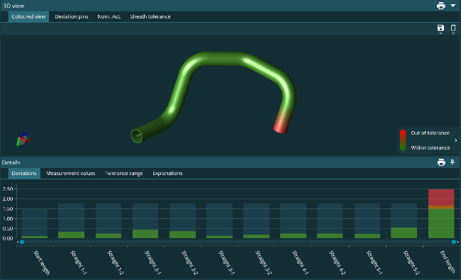
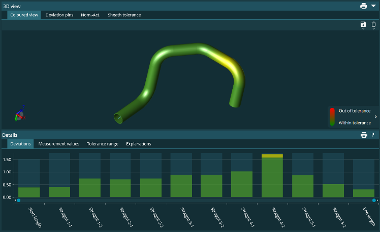
For the example we are discussing, the initial inspection results showed the B end of the tube as long. After making the single change of including the start and end lengths in the best-fit alignment, the part passed inspection. The area of highest deviation is evident at Straight 4-2. When looking at the fit of the part in the gauge, it is clear that this area is also the tightest fit on the gauge.
When creating inspection plans, it is important to consider all elements of the inspection including the alignment. It is easy to simply use the default settings but as seen in this example, that is not the best approach. Especially when comparing to a physical checking fixture, one must ensure that the alignment and inspection criteria are set appropriately to inspect in the same way as the gauge. When done properly, users will see very strong correlation between the virtual/digital gauge of TubeInspect/BendingStudio and physical checking fixtures.